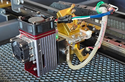
Hello, I have a 50w CO2 40x40 machine that I upgraded with a second head, the A40640 that complements the capabilities of IR CO2 in a very interesting way.
I was able to integrate the second head because I have a RuiDa RDC6445 controller that supports a second head and offers all the parameters you need to control even a Laser Diode head.
I used the RDWorks software to set up all the offset and alignment parameters and now my unit has the two beams perfectly superimposed. I also added a webcam on the lid so that I can see the objects on the cutting plate and place the art with great precision. RDWorks, again, supports this feature and I find it very useful.
This is my dual head setup. I lasercut a thick acrylic mounting bracket and secured it on the existing CO2 system. I am using the slide mount to remove the A40640 when I need fast CO2 activities as its weight could produce vibrations and streee sthe motors.
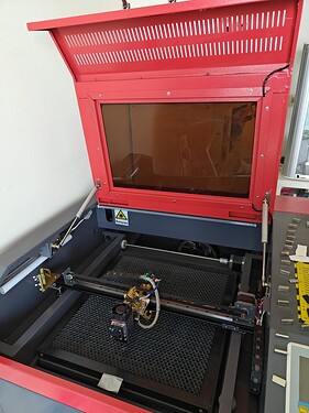
This is the overall view. The webcam is just under the handle of the cover and has a perfect view of the whole cutting area.
Going to the topic of this post, I know that Steel oxidises with different colors according to the temperature it reaches; the 450nm radiation is absorbed by steel and therefore the energy is converted in heat and this opens the way to coloring. Each 450nm laser head has its own spot size, energy density and power, therefore the coloring process requires some investigation and experimentation before you find the proper settings that generate the colors. It is a process similar to the one you do to find the parameters for etching and cutting different materials.
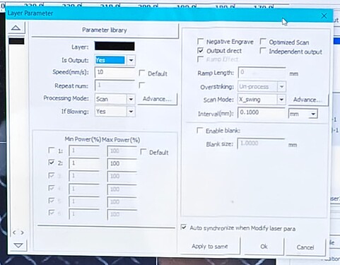
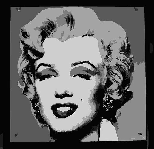
I use RDWorks and the SCAN mode for bitmaps and vectors, with the direct output mode. This translates the grayscale value into power and this creates a direct link between the color and the value of the grayscale. Both they have to be managed as 0 to 100% and not 0x00 to 0xFF (0 to 255 DEC).
If you have a different controller, I think you can still apply the same logic, as far as your software takes the values of the grayscale to drive the power of the laser. My speed is 10mm/sec and as you may imagine, you can go slower or faster changing the outcome of the color for the exact same power.
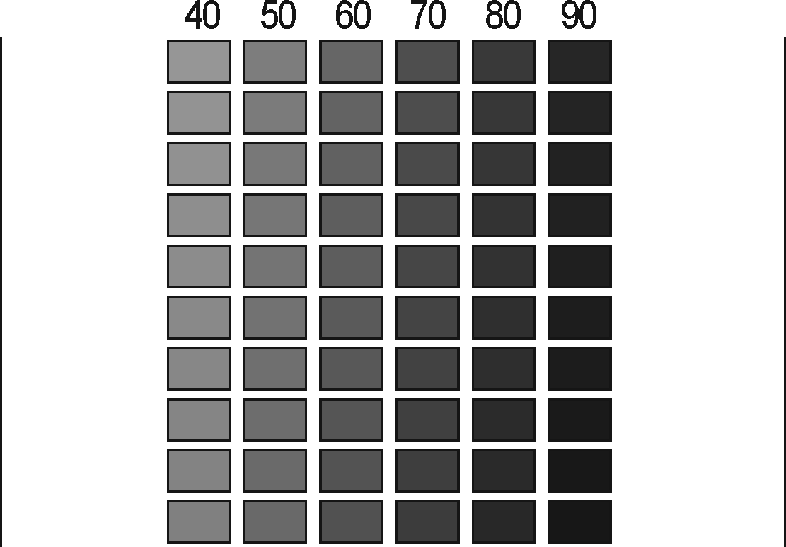
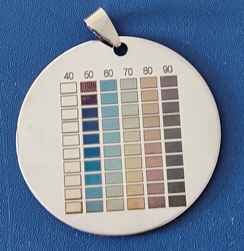
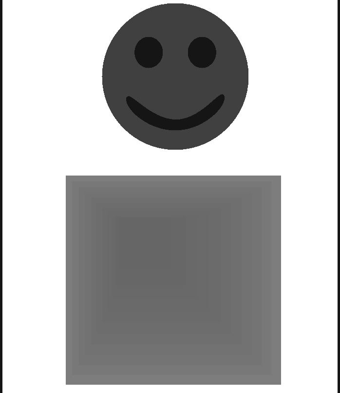
Here is a matrix of grayscale values from 40 to 99%. I have added two thin lines at the sides because I found that when the head reverses direction there is a slight vibration that for the delicate coloring process is problematic. The line forces the head to reverse direction away from the areas to color.
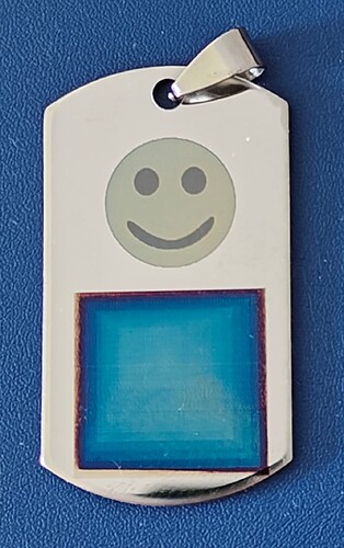
And this is this the result with my machine and my parameters (shown in the RDWorks panel)
I intentionally reduced the matrix to the values you see because the lower values do not have effect at reasonable speed. The 90 to 99 series has little effect and therefore you can speed up by 1 to 4 mm/sec shifting the colors one column to the right. EXPERIMENTATION and precise focusing (repeatability) are absolutely fundamental to get your results.
The tags I use are sourced from Aliexpress and work great both on mirror and brushed sides.
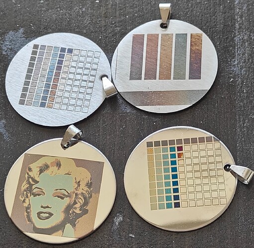
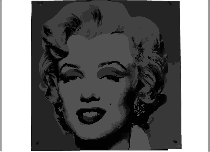
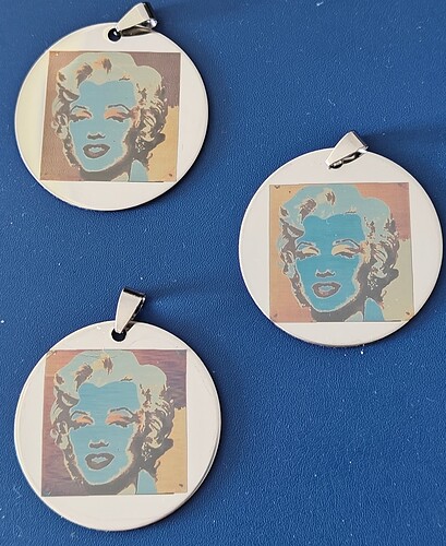
When you have found your parameters (speed and focus), you can start to priduce something more interesting than the color matrux. Here are a few examples of my creations…
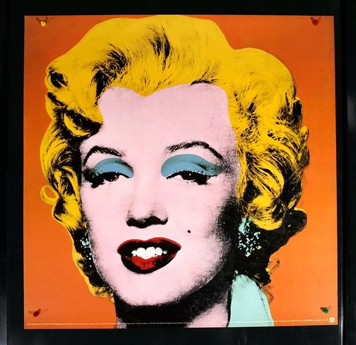
And this is with another subject.
Please note how a 1% difference in the grayscale for the square has a huge impact on color.
I hope this information will inspire your creations. Coloring steel is really fun and requires some patience, but the reward is worth the hassle.
If you want to get more information about the science behind this effect you can google “steel color temperature chart”.
Happy coloring
Simone
PLEASE NOTE: steel is like a mirror and a LOT of the laser energy is reflected. ALWAYS wear protective googles when coloring steel or your eyes will be damaged
